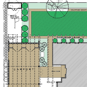
This is also true with shelving where there is a top shelf that projects a certain distance and underneath the shelve are smaller sized shelves that do not project as far. The edge where the projection of the nosing begins is shown as dotted or dashed on the stair plan. An example of this is the nosing on a stair tread.

Hidden EdgesĪnother common use of the dotted line is to illustrate the edges of objects that are hidden from view. For example, a dishwasher that is underneath the kitchen countertop would be illustrated using a dotted line (or small dashes) to indicate that it is below the surface shown on the plan. This might include objects that are underneath the surface of the reference plane. So if you are seeing a dotted line on a plan, it’s more likely that you are dealing with hidden elements. While not set in stone, it’s common convention to use longer dashes to convey elements that are removed or above the plane and shorter dashes or dots for hidden elements below the plan cut. Also, corners should always be “squared off” with dashes of equal size in order for the referenced object to read more clearly. This allows the reader to more quickly understand what is being referenced. It’s important that the size of the dashes and the spacing be consistent throughout the plan where the same type of element is described. The size of the lines may vary from element to element in order to distinguish one type of object from another, in particular if the plan is complex and has many types of referenced elements. Graphic ConventionsĪ dotted or dashed line is composed of a series of very small lines of consistent size that are regularly spaced. Let’s take a more detailed look at some common uses. For this reason, context is important in determining what the specific dotted or dashed line represents.

They may sometimes be used to represent the implied extension of an edge or boundary or to call out a reference area. Likewise, dashed lines can be used to denote objects that are in front or in the back of a reference plane. This includes elements that are either above the plan cut or underneath the surface of elements within the plan.

After seeing them, you may wonder what they represent and why they are illustrated differently from other lines on the architectural or engineering plan.ĭotted or dashed lines on a floor plan indicate elements that are hidden or removed from view.

When reviewing floor plans you may have come across portions of the drawing that are shown with dotted or dashed lines.


 0 kommentar(er)
